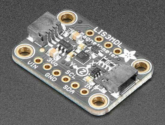
Mfr Part # 5543
ADAFRUIT LSM6DS3TR-C + LIS3MDL -
Adafruit Industries LLC
License: See Original Project Arduino
Courtesy of Adafruit
Guide by Lady Ada
Overview
AHRS is an acronym for Attitude and Heading Reference System, a system generally used for aircraft of any sort to determine heading, pitch, roll, altitude etc.
A basic IMU (Intertial Measurement Unit) generally provides raw sensor data, whereas an AHRS takes this data one step further, converting it into heading or direction in degrees.
To help you get started designing your own AHRS system, or just to help convert raw sensor data into useful numbers that you can relate to the real world, we've created an Arduino library that lets you 'fuse' a range of common accelerometer/gyroscope/magnetometer sensor sets using a few different algorithms such as Mahony, Madgwick, and NXP Sensor Fusion.
We recommend a Cortex M0 or faster/greater chipset - there's a lot of math and memory required so 4KB+ or RAM and 32 MHz+ speed helps for the fancier algorithms. That said, you can do some basic fusion with an ATmega328p (Arduino UNO compatible). The data is output on the serial port for easy integration.
Storing Calibrations
Every sensor will vary and need calibration. Some sensors have a 'range' for their error output, which helps us know if the sensor is functioning - but we still need to calibrate every sensor/board. One of the challenges with per-device-calibration is how to store that calibration.
We could put the calibrations at the top of the Arduino sketch, but we would have to re-compile it for each device, and it’s also easy to forget or lose the calibration.
So, instead, we try to store the calibration in non-volatile memory - that means either EEPROM or external FLASH. We try to use external flash not internal flash, because internal flash can be erased and overwritten when we upload new code.
There's lots of different ways you could save calibrations - but to make things easiest we're going to stick to those two techniques. However, that means our board has to have some sort of NVM available! Here's what you can expect:
EEPROM Memory (either real or simulated)
Some chips have EEPROM memory, this is a tiny amount of memory, which is separate from FLASH, where you can tuck maybe 256 bytes of data. There's two kinds of EEPROM, 'real' and 'simulated'. Real is, well, real! There's literally a chunk of memory inside the chip itself, and you'll see it mentioned in the datasheet as EEPROM.
The ATmega328 datasheet indicates that you can get up to 1KB of EEPROM (depends on which model of the chip you buy.)
It’s not terribly common to see EEPROM in chips as you get to the more expensive models. Partially that's because they tend to have SPI Flash chips, but also cause they aren't that useful with larger chips. Either way, simulated EEPROM is when some internal SPI flash or external memory storage is dual used as EEPROM. For example, the ESP8266 uses the very end of the SPI flash chip that holds the program memory for EEPROM.
Some chips with real EEPROM:
Some chips with simulated EEPROM:
External SPI or QSPI memory
This is a separate chip used to store files, code, audio, graphics, etc. A lot of Adafruit products have SPI/QSPI memory in order to support CircuitPython. For example:
The reason we prefer external memory is that you can edit the file using any text editor, when CircuitPython (or another mass-storage enabled sketch) is loaded. Also, many of the above do not have EEPROM, so there's often not a choice.
The Feather M0 Express has an 8-SOIC SPI Flash chip highlighted to the left.
The only thing to watch out for is that the SPI FLASH must be formatted with a filesystem - much like an SD card (altho, these days, SD cards come pre-formatted). A blank SPI Flash chip doesn't have anything on it.
Manually Setting in Code
The least desirable, but sometimes necessary, option is to simply set the calibration at the top of your sketch/code. It's not something we like to do because it’s easy to lose the calibration, but it's always an option!
Calibration Pre-Check
OK before we continue, we have to check that we are able to store calibration either in the EEPROM (ATmega328, 'm32u4, 'm2560, ESP8266, ESP32) or (Q)SPI Flash (most Adafruit M0, M4, nRF52840 boards.)
Library Installation
You'll need a few libraries, install them through the library manager!
Search for and install Adafruit Sensor Calibration.
We strongly recommend using Arduino IDE 1.8.10+ because it will automatically install any dependency libraries. If you have to install manually, grab SdFat - Adafruit Fork, ArduinoJson, Adafruit SPIFlash, Adafruit Unified Sensor as well (see all dependencies here.)
Compilation & Upload Check
Load sensor_calibration_read example - yes even though there is no calibration yet, this will let us verify the basics!
EEPROM Storage
First, we'll try loading it into a chip with EEPROM (an ATmega328-based Metro mini!)
Here's what you should look for:
If you got this far, you're good! Go to the next page where we try to write calibrations.
Flash Storage
Here's what you can expect if you're using a chip with built in SPI/QSPI storage!
Here's what you should look for:
If you got this far, you're good! Go to the next page where we try to write calibrations.
Flash Unformatted Error
There's a chance, if you have a totally fresh board, that the flash is unformatted. In this case, when you upload the calibration reader, you'll get that the JEDEC Chip ID was read (it may vary), and that the flash size was detected - but failed to mount newly formatted filesystem!
If that happens, you have two ways to format the filesystem.
Compile, upload and check the serial monitor for instructions.
Now re-upload/re-try the sensor calibration reading demo.
Calibration Write Check
OK now that we have our calibration storage worked out, let’s try writing a calibration to disk!
Load up the other example, sensor_calibration_write
You'll see that we first load any existing calibration from non-volatile storage with cal.loadCalibration(). Then we set the calibrations we want to save with:
// in uTesla
  cal.mag_hardiron[0] = -3.35;
  cal.mag_hardiron[1] = -0.74;
  cal.mag_hardiron[2] = -40.79;

  // in uTesla
  cal.mag_softiron[0] = 0.965;
  cal.mag_softiron[1] = 0.018;
  cal.mag_softiron[2] = 0.010;
  cal.mag_softiron[3] = 0.018;
  cal.mag_softiron[4] = 0.960;
  cal.mag_softiron[5] = 0.003;
  cal.mag_softiron[6] = 0.010;
  cal.mag_softiron[7] = 0.003;
  cal.mag_softiron[8] = 1.080;

  // in Radians/s
  cal.gyro_zerorate[0] = 0.05;
  cal.gyro_zerorate[1] = -0.01;
  cal.gyro_zerorate[2] = -0.01;
which only changes the calibrations in temporary memory. Finally, we run cal.saveCalibration() to write the calibration to permanent storage.
Upload this to your board.
EEPROM Example
If you use a chip with EEPROM, you'll see similar output from the previous page, this time you will get to see the HEX data stored in EEPROM. We use the same format as PJRC's NXPMotionSense library so you will see 0x75, 0x54 as the first two bytes of the data chunk.
External FLASH example
If you use a chip with external flash, you should see similar output from the previous pre-check, but now it will write the calibration and also print out calibration file for you. You can see that it's stored in JSON format for easy parsing in Python or Arduino!
Reading back calibration
OK no matter which way you calibrated, now you can load the calibration read example to see the saved values loaded up and printed out!
For EEPROM:
For external FLASH:
Magnetic Calibration with MotionCal
Calibrating the magnetometer is required to get good orientation data!
Before running this example - make sure you have done the calibration pre-check and write check!
Paul Stoffregen of PJRC wrote a really awesome cross-platform calibration helper that is great for doing both soft and hard iron magnetometer calibration. What's nice about it is you get a 3D visualization of the magnetometer output, and it also tosses outliers and tells you how much spherical coverage you got!
Step 1 - Download MotionCal Software
MotionCal is available for Mac, Windows and Linux, you can download it from clicking here.
Look for this section on the website:
And click the one that matches your computer the best.
Step 2 - Configure & Upload the AHRS calibration Example
Next, we have to tell the microcontroller board to send the magnetometer (and, if there is one, accelerometer and gyroscope) data out over serial in the right format.
Open up the Adafruit_AHRS->calibration example.
At the top of the sketch, you'll see a section where you can #include different sensor sets. Not every sensor-set is defined, but our most popular ones are! (You'll need sensors that are Adafruit_Sensor compatible.)
Uncomment whichever kit you are using, and comment out the rest.
Select your desired board & port from the Tools menu then click Upload.
Open up the serial console and check that the EEPROM/Filesystem was found. There may already be an existing calibration from prior experiments.
You'll then see a stream of data that looks like:
Raw:-58,-815,8362,76,-121,-95,-375,-159,-24
Uni:-0.07,-0.98,10.00,0.0832,-0.1327,-0.1046,-37.50,-15.93,-2.50
The first three numbers are accelerometer data - if you don't have an accelerometer, they will be 0.
The middle three numbers are gyroscope data - if you don't have a gyroscope, they will be 0.
The last three numbers are magnetometer, they should definitely not be zeros!
Step 3 - Run MotionCal
Close the serial port, and launch MotionCal.
Select the same COM/Serial port you used in Arduino.
Twist the board/sensor around. Make sure it’s not near any strong magnets (unless that's part of the installation.)
Keep twisting until you get a complete 'sphere' of red dots. At this point you are calibrated!
In the top right you'll see the hard magnetic offsets at the top, the soft offsets in the middle and the field strength at the bottom.
In this case, the hard iron offsets are [-31.25, 35.67, -116.44]
Take a screenshot of this display, so you can refer to these numbers later!
MotionCal does not calibrate the accelerometer or gyroscope (yet) - so those offsets will be zero.
Eventually you'll have enough datapoints that the Send Cal button will activate (its grayed out by default.)
Once you can click the button, try clicking it (we had to try a few times?)
You'll see a large green checkmark once the calibration is saved and verified!
Step 4 - Verify Calibration
Re-load the sensor_calibration_read sketch to verify the calibration was saved!
Sensor Fusion Algorithms
There's 3 algorithms available for sensor fusion. In general, the better the output desired, the more time and memory the fusion takes!
Note that no algorithm is perfect - you'll always get some drift and wiggle because these sensors are not that great, but you should be able to get basic orientation data.
In order of complexity, they are:
Mahony
This basic but effective algorithm will run on smaller chips like the '328p which makes it a great one for any platform.
The original paper is available here
Madgwick
This algorithm is very popular when you have faster Cortex M0, M3, M4 or faster chips. It isn't going to run on an atmega328p.
The original paper is available here
NXP Sensor Fusion
This really nice fusion algorithm was designed by NXP and requires a bit of RAM (so it isn’t for a '328p Arduino) but it has great output results.
As described by NXP:
Sensor fusion is a process by which data from several different sensors are fused to compute something more than could be determined by any one sensor alone. An example is computing the orientation of a device in three-dimensional space. That orientation is then used to alter the perspective presented by a 3D GUI or game.
The NXP Sensor Fusion Library for Kinetis MCUs (also referred to as Fusion Library or development kit) provides advanced functions for computation of device orientation, linear acceleration, gyro offset, and magnetic interference based on the outputs of NXP inertial and magnetic sensors.
Version 7.00 of the development kit has the following features:
The fusion library is supplied under a liberal BSD open-source license, which allows the user to employ this software with NXP MCUs and sensors, or those of our competitors. Support for issues relating to the default distribution running on NXP reference hardware is available via standard NXP support channels. Support for nonstandard platforms and applications is available at https://community.nxp.com/community/sensors/sensorfusion.
Let's fuse!
OK now that the sensors are calibrated, and you know what the options are for filters - it’s time to FUSE THOSE SENSORS! That's what we're here for, right?
Install the Adafruit AHRS library from the library manager. We strongly recommend using Arduino IDE 1.8.10+ because it will automatically install any dependency libraries. See all dependencies here.
Open up the calibrated_orientation sketch.
At the top of the sketch, you'll see a section where you can #include different sensor sets. Not every sensor-set is defined, but our most popular ones are! (You'll need sensors that are Adafruit_Sensor compatible.)
Uncomment whichever kit you are using and comment out the rest.
// uncomment one combo 9-DoF!
#include "LSM6DS_LIS3MDL.h"  // can adjust to LSM6DS33, LSM6DS3U, LSM6DSOX...
//#include "LSM9DS.h"           // LSM9DS1 or LSM9DS0
//#include "NXP_FXOS_FXAS.h"  // NXP 9-DoF breakout
Next, you can select which fusion algorithm you want to try:
// pick your filter! slower == better quality output
//Adafruit_NXPSensorFusion filter; // slowest
Adafruit_Madgwick filter;  // faster than NXP
//Adafruit_Mahony filter;  // fastest/smalleset
By default, we'll be performing a calculation every 10 ms (100Hz) and printing out 1 out of 10 calculations, however you can adjust those numbers up or down in this section as well as adding debug output.
#define FILTER_UPDATE_RATE_HZ 100
#define PRINT_EVERY_N_UPDATES 10
//#define AHRS_DEBUG_OUTPUT
OK now compile & upload!
Open the serial console and you'll see the sensors detected and then text like this.
Orientation: 180.82 -1.65 2.48
These are the Euler angle outputs from the fusion algorithm.
You'll also see text like
Quaternion: 0.7545, 0.2937, 0.5858, -0.0356
These are the quaternion outputs.
Euler Angles
Euler angles describe orientation (in degrees) around a single reference point in three-dimensional space.
Various names are employed for the three angles, but the most common terminology with aircraft is Roll (x), Pitch (y) and Yaw (z).
The illustration below from the Wikipedia article on Euler angles should illustrate the concept clearly. You normally have both positive and negative angles (-180° to 180°) depending on the direction the airplane is tilted, with 0° in every direction corresponding to the airplane being perfectly aligned with each axis:
The printout of data is in Yaw (Z) Pitch (Y) Roll (X) order, so if you get
Orientation: 163.00 -4.90 33.56
The yaw is 163 degrees, pitch is -4.90 degrees and roll isare about 33.56 degrees. The sketch will keep updating itself with the latest values at whatever speed we've set in the example sketch.
Try twisting the sensor along each axis as printed on the sensor breakout/PCB to see the numbers change from -180~180 for each axis.
WebSerial Visualizer
Those three numbers are fine and good, but we want to see what they mean in 3D space, right? Traditionally, a Processing sketch would be used to read the serial data and convert it to a 3D rotation - but thanks to Web Serial API we can use any Chrome browser - a lot easier than installing Processing!
Step 1 - Install Chrome
Start by installing the Chrome browser if you haven't yet.
Step 2 - Enable Web Serial API if necessary
As of Chrome 89, Web Serial is enabled by default.
At the time of this tutorial, you'll need to enable the Serial API, which is really easy.
Visit chrome://flags from within Chrome. Find and enable the experimental web platform features.
Restart Chrome
Step 3 - Visit the Adafruit 3D Model viewer
In Chrome, visit https://adafruit.github.io/Adafruit_WebSerial_3DModelViewer/
Verify you have 115200 Baud selected (it only really matters for non-native-serial devices but might as well make sure it’s right.)
Click Connect
When the security window pops up, pick the matching Serial/COM port for your board running the AHRS sketches. Make sure the serial port isn't open in Arduino or something.
You'll see the serial port monitor on the bottom and a 3D bunny on the top. Try rotating and twisting the sensor to see it move!