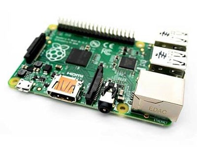
Mfr Part # SC0193(11)
SBC 1.5GHZ 4 CORE 2GB PI 4 MOD B
Raspberry Pi
License: See Original Project
Monitoring CPU utilization while performing demanding tasks or running custom programs can give you crucial insights into the necessary processing power. Establishing baseline measurements is vital for optimizing source code to run more efficiently on the target platform.
While command-line tools offer precise performance indicators, they are not engaging and are often overly complicated to review for many applications for determining if a CPU core is consistently maxed out or if operating at partial utilization suffices. This project employs analog-style voltmeters to give you an engaging, stunning, and practical readout of your Raspberry Pi's CPU load.
Required Components
While you can adapt this project to run on any Raspberry Pi, I recommend using one of the later models with a quad-core CPU. The more modern CPUs are more difficult to max out, meaning the meters have more values to display than just 0% or full utilization. Further, employing four analog voltmeters — one for each CPU core — makes for a more intriguing effect than using a single voltmeter that displays the average utilization.
Besides a Raspberry Pi, if you wish to recreate this build, you will need four analog-style voltmeters with an appropriate voltage range. All newer Raspberry Pi models output a maximum of 3.3V through their GPIO pins, so a meter like this one that goes from 0V to +3V is perfect for this application.
Wiring the Voltmeters
Connecting the voltmeters to the Pi requires only a few jumper wires with a female end that can plug right into the GPIO pins. Usually, the other end of the wire gets secured using screw terminals attached to the panel-mount voltmeters.
The screw terminals for measuring the voltage and the mounting screws are positioned as shown above.
Each meter requires two connections: a positive wire that can be connected to any digital output pin and a GND wire. You can choose whether to connect the other terminal of each voltmeter to a separate GND pin on the GPIO or combine all the wires, depending on whether you need to preserve some free ground pins for other external parts.
The schematic diagram of this project. Source: Scheme-it
Installing the Required Libraries
The application requires you to install the psutil library using pip:
pip install psutil
Translating CPU Utilization Values to Voltages
A simple background program must read the current CPU load and translate it to a voltage between 0V for an idling core and 3.3V when it runs at full steam. The Raspberry Pi doesn't have analog outputs, so the program can only send high or low states via the Pi's GPIO pins. However, using pulse-width modulation (PWM), the program can average the output voltage so that the meter still displays the desired value.
PWM can generate analog-like signals by varying the duty cycle of a digital square wave. The duty cycle represents the ratio of time the signal is on to the total period of the signal. So, for example, a 50% duty cycle means that the output signal is high for 50% of its period, leading to an average output of 1.5V. Adjusting the duty cycle allows you to control the average voltage to mimic an analog output's behavior.
import psutil
import RPi.GPIO as GPIO
import time

pin_numbers = [17, 18, 27, 22]
pwm_pins = []
pwm_frequency = 5000

# Set up GPIO mode and pins for PWM
GPIO.setmode(GPIO.BCM)

for i in range(0, len(pin_numbers)):
    pin = pin_numbers[i]
    GPIO.setup(pin, GPIO.OUT)
    pwm_pin = GPIO.PWM(pin, pwm_frequency)
    pwm_pin.start(0) # Start with a duty cycle of 0%
    pwm_pins.append(pwm_pin)

try:
    while True:
        # Read CPU load per core
        cpu_loads = psutil.cpu_percent(percpu=True)
        # Update PWM duty cycle based on CPU load
        for i, load in enumerate(cpu_loads):
            pwm_pins[i].ChangeDutyCycle(load)
        time.sleep(0.25)
except KeyboardInterrupt:
    pass
finally:
    for i in range(0, len(pwm_pins)):
        pwm_pins[i].stop()
    GPIO.cleanup()
The program first imports the previously installed libraries necessary to read the current CPU utilization and communicate with the GPIO pins. The program stores the pin numbers in a list to make it easy to access them using only an index. The next line sets the PWM frequency to 5 kHz. A sufficiently fast signal ensures the voltmeter’s needle doesn’t fluctuate erratically. The script then sets the GPIO driver’s mode to use the BCM pin numbering scheme.
Next, the script initializes all PWM pins using a for-loop that iterates over all the previously defined pin numbers. Using a list of numbers and their indices saves repeating numerous lines of code and makes the program easier to adapt for platforms with more than four processing cores. The program stores the created PWM objects in a new list.
The program defines an endless while loop that runs until you exit the program manually. Within the loop, the script reads the CPU utilization per core in percent ranging from 0 to 100 and then changes the duty cycle of each output pin to correspond to the readout value. Finally, the program waits a quarter of a second before repeating the loop. The very last loop in the program stops the PWM output and frees the GPIO hardware resource when you decide to exit the program using the keyboard interrupt command (CTRL + C).
The following command runs the program as a background process:
python3 cpu_meter_firmware.py &
Building a Case
You can get creative when making a case for your analog-style CPU utilization monitor. I decided to go for a steampunk look by gluing some copper pipes and fittings from the hardware store. I then drilled holes in the pipes and mounted a thin plywood sheet using nuts and bolts:
The steampunk look was the inspiration for this assembled case.
The plywood sheet has mounting holes for the voltmeters, which are held in place by the screws that came with them. I then tucked away the wires and attached the pipe construction to a wooden base with space for the Raspberry Pi:
With the wiring in place, the Raspberry Pi sits on the base plate.
Summary
This beginner-friendly project doesn’t require soldering, as the wires plug right into the Raspberry Pi’s GPIO pins on one side and get attached to the analog voltmeter using built-in screw terminals.
The needles move independently of each other.
The firmware for this project reads the CPU utilization per core and translates those values to a voltage level between 0V, which indicates an idling core, and 3.3V, which corresponds to a maxed-out processing core. The program uses PWM to mimic an analog output by altering the square wave signal’s duty cycle, which works well with voltmeters that are slow to respond.
Using only a few cheap components, you can create a visually stunning CPU utilization readout that is functional and acts as an impressive centerpiece or conversation starter.