How to Apply Hybrid AC Surge Protection Devices for Improved Surge Protection
Contributed By DigiKey's North American Editors
2022-09-07
Electronic devices are pervasive and advancing rapidly with increasingly sensitive circuitry that depends heavily on front-end protection as they access electrical infrastructure, that may or may not have the most up-to-date protection against voltage surges and transients. These transients can be the result of lightning strikes, switching, or similar voltage surge incidents that can cause overvoltage and overcurrent events that may damage or otherwise degrade sensitive electronic devices.
Existing low-cost surge protection technologies, such as gas discharge tubes (GDTs) and metal oxide varistors (MOVs), divert or limit the surge energy thus preventing it from reaching the protected device. Each has its respective advantages, but both of these devices have limits to the number of transients they can handle before they fail. Also, GDTs may not shut off current completely, while MOVs may be subject to failure due to thermal runaway after a number of transient event activations.
To capture the best of both GDTs and MOVs, while mitigating their deficiencies, hybrid technology components have emerged in a single integrated device with a comparatively smaller physical size for a given level of surge protection. While the complementary nature of the integrated components improves the performance of both and extends their operational life, to be effective, careful matching of the GDT and MOV elements is required. Implemented correctly, these IsoMOV™ hybrid surge protectors are especially useful for ensuring compliance with IEC/UL62368-1, a hazard-based standard for information technology and audio/visual equipment.
This article briefly discusses how GDT and MOV surge protectors operate before examining the characteristics of real-world IsoMOV hybrid protector examples from Bourns. It concludes by showing how to implement IsoMOV technology to meet IEC/UL62368-1.
How do SPDs work?
Surge protection components operate in one of two ways - they may operate as a switch, diverting the surge to ground (sometimes called crowbarring), or they may limit the surge voltage by clamping the maximum voltage to a reduced level by absorbing and dissipating the transient energy.
The GDT is an example of a crowbar limiter. It consists of a spark gap in a nonreactive gas like argon and is wired across the power line. If the voltage level is below the GDT breakdown voltage, the device is basically in a high impedance “off” state. If a transient increases the voltage level above the GDT’s breakdown voltage, the GDT goes into a conducting - or “on” - state (Figure 1).
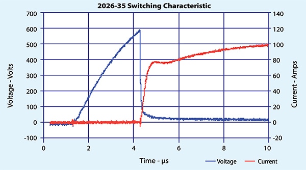 Figure 1: Shown are the voltage and current waveforms for a GDT being triggered on. Once the breakdown voltage is exceeded, the voltage falls to about 10 volts, and the current increases significantly. (Image source: Bourns)
Since the GDT is wired across the power input, it basically shorts out the power source. This triggers a fuse, circuit breaker, or other serial protective device, thereby protecting the circuits downstream of the GDT. Note that in the off state, the voltage is high, and the current is low. In the on state, the opposite occurs and the dissipated power is very small, except at the transition between states. Resetting the state of the GDT requires that the input voltage be reduced below the breakdown voltage. In the event that the power line input does not drop low enough, the GDT may not reset and continue to conduct a “follow-on” current, keeping it on. The possibility of the GDT staying on is a significant limitation for this type of surge protection technology.
The MOV is a clamping device. Like the GDT, it is placed across the power line. In normal operation, the MOV is in a high impedance state and draws only a small leakage current (Figure 2).
 Figure 2: The current-voltage characteristic of an MOV shows the bipolar clamping action. (Image source: Bourns)
In the event of a voltage surge, the impedance of the MOV falls and draws more current, dissipating the power; this reduces and limits the voltage of the transient. When the transient ends, the MOV impedance increases and returns to its normal state. MOVs are rated based on the number of such transient events they can tolerate. After a number of transient events, the leakage current of the MOV may increase. This increases the power dissipated by the device, causing it to heat up. Heating increases the leakage current and may cause the MOV to enter thermal runaway, resulting in a catastrophic device failure.
Neither of these surge protection technologies by themselves is ideal. However, if the GDT and MOV are placed in series across the power line, their complementary behavior becomes clear. In normal operation, the GDT is off, and there is no leakage current flow in the MOV. During a voltage transient the GDT fires, thereby placing the MOV in the circuit. The MOV then clamps the transient voltage surge. When the transient has passed the MOV turns off, reducing the current through the GDT, allowing it to turn off as well.
For the GDT and MOV to be placed in series requires careful matching of their characteristics so that they complement each other precisely. Discrete implementations are subject to a wide range of variables from design through manufacturing, testing, and packaging - making it challenging for designers to find good matches. To address the challenges, Bourns’ IsoMOV hybrid protectors combine a carefully matched set of MOVs and a GDT element into a single package that is much smaller than the individual components (Figure 3).
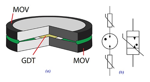 Figure 3: The IsoMOV SPD is formed by incorporating the GDT between two MOVs (a). The composite schematic symbol is shown on the right in (b). (Image source: Bourns)
The composite transient voltage response of the IsoMOV hybrid protector in Figure 4 shows how both elements work together.
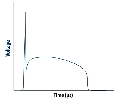 Figure 4: The voltage response of the IsoMOV hybrid protector shows the GDT component breaking down to activate the MOV components, protecting the downstream circuits. (Image source: Bourns)
Both elements of the IsoMOV hybrid protector are engineered to independently withstand the maximum continuous operating voltage (MCOV). As mentioned, the GDT blocks the MOV leakage currents when there is no transient present. Even after many transients, the GDT cuts off the rising MOV leakage current levels. The MOV prevents the follow-on current after a transient surge, thereby protecting the GDT. The geometry of the IsoMOV device increases the surge capacity per unit area compared to a single MOV.
From a design engineer’s perspective, IsoMOV devices provide enhanced protection in a small integrated package that minimizes both component count and board space. For example, the ISOM3-175-B-L2 is an IsoMOV hybrid protector with an MCOV of 175 volts root mean square (VRMS), capable of handling at least fifteen 3 kilo ampere (kA) nominal surges with a maximum clamping voltage of 470 volts (Figure 5). It has a diameter of 13.2 millimeters and a thickness of 6.1 mm. The diameter varies with the maximum current capability, and the thickness increases with an increasing MCOV.
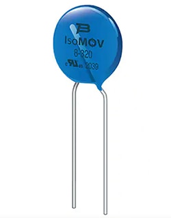 Figure 5: The ISOM3-175-B-L2 is an example of the IsoMOV hybrid protector’s compact form factor. Although it includes two MOVs and a GDT, it measures just 13.2 mm in diameter with a thickness of 6.1 mm. (Image source Bourns)
The Bourns IsoMOV family includes three distinct nominal current ratings of 3 kA, 5 kA, and 8 kA, with MCOV ratings from 175 to 555 VRMS. The mid-range devices include the ISOM5-300-B-L2, a 300 VRMS, 5 kA device with a diameter of 17 mm and a thickness of 7.1 mm. At the high current end is the ISOM8-555-B-L2 which is an 8 kA device with a 555 VRMS MCOV. It has a diameter of 23 mm and a thickness of 9.4 mm. All of these devices have an operating temperature range of -40°C to +125°C.
Bourns’ IsoMOV hybrid protectors offer these state-of-the-art surge ratings in a space-saving form factor compared to using separate MOVs and GDTs. They have ultra-low leakage currents, and the series GDT extends the life of the MOV. Additionally, all IsoMOV SPDs are listed as UL1449 type 4 components, making it easier to design them into surge protection devices.
Implementing protection to IEC/UL62368-1 levels
IsoMOV components are useful solutions for achieving compliance with IEC/UL62368-1. The new IEC/UL 62368-1 safety standard for audio/visual and information communications technology equipment, is based on the Hazard Based Safety Engineering (HBSE) principles for the physical safety of equipment users and the realization of safety measures. It identifies potentially hazardous energy sources and the processes by which energy can be transmitted to a user, both in normal operation and under faulty conditions.
The recommended power input protection design in Figure 6 includes protective devices from line to neutral, line to protective ground, and neutral to protective ground.
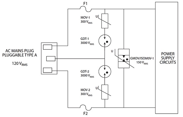 Figure 6: The recommended power input protective circuit consistent with IEC/UL62368-1 has protective devices from line to neutral, line to protective ground, and neutral to protective ground. (Image source: Bourns)
The GDTs in series with MOVs or IsoMOVs between line and ground or neutral to ground are needed to protect from electric shock that could occur if an MOV were used alone. If the protective ground was not connected, the leakage current of the MOV alone might be high enough to cause injury if the user touched the isolated ground path. Placing the GDT in series eliminates that leakage current.
Hazards associated with MOVs and devices containing MOVs include shock due to excessive leakage currents and the possibility of fire. Due to their failure mode, MOVs are considered potential ignition sources (PIS), requiring that the design includes steps to reduce the possibility of ignition and block the spread of any fire.
Surge protectors help increase product reliability and must conform with specific tests required by the standard. For example, The MCOV of an MOV must be at least 1.25 times the upper voltage limit of the equipment voltage range. For equipment with a power input range of from 85 to 250 volts AC, the minimum MCOV for a line protection MOV in that equipment should be 313 volts. Line protection circuits that include an MOV across the line are subject to a test based on a line voltage of twice the nominal rating. The input current is sequentially limited by resistors to values of 0.125, 0.25, 0.5, 1, and 2 A. Since the MOV is a potential fire source, testing continues until the MOV fails. This test is not required for MOVs with MCOV greater than two times the maximum rated line voltage due to the very low possibility of MOV failure under those conditions.
Conclusion
IsoMOV hybrid protectors provide improved and more compact protection for electronic systems as they advance, shrink, and proliferate at an accelerating rate, against a backdrop of aging or poorly protected infrastructure and ever-evolving user protection standards. Along with exceptional performance and space savings, they have an extended temperature range, low leakage, and high energy-handling capability. While they are especially advantageous to industrial applications exposed to high surges, they can be readily implemented in audio/visual and information communications technology equipment to meet the IEC/UL62368-1 standard based on Hazard Based Safety Engineering (HBSE).

Disclaimer: The opinions, beliefs, and viewpoints expressed by the various authors and/or forum participants on this website do not necessarily reflect the opinions, beliefs, and viewpoints of DigiKey or official policies of DigiKey.


