High-Voltage Power Modules Simplify Control System Design
Contributed By Electronic Products
2014-01-28
Voltage requirements for industrial control systems are on the rise. For example, the integration of Power-over-Ethernet (PoE) into these systems is encouraging designers to migrate their legacy 24 V power to the 48 V demanded by the new technology.
These systems demand that input voltages need to be converted to 5 or 3 V (or even lower) to supply the electronics. A traditional solution for creating one or more of these low-voltage rails comprised low-voltage controller with additional drivers, field-effect transistors (FETs), and sometimes transformers; and a high step-down ratio is often involved in more than one power stage.
However, modern control systems use compact, modular units to house the component parts, so space is tight. This has led to demand for electronics that do not require space-consuming forced cooling. Replacing the traditional power supply with the compact, efficient, silicon-based power modules preferred by consumer electronics designers is an answer to this challenge.
However, switching to silicon power is not easy because, while the nominal voltages of industrial control systems are within the capability of modern integrated switching DC/DC voltage regulators, voltage spikes of up to 100 V are not uncommon. Such transient overvoltages are sufficient to destroy a silicon regulator in seconds. Engineers are forced to add expensive and voltage-clamping networks to protect sensitive silicon power supplies, increasing design complexity, using up space and adding cost.
Fortunately, a new generation of wide-input voltage, integrated silicon power supplies are becoming available that can tolerate large voltage spikes without incurring damage or exposing downstream circuitry to the transients. This article describes some of these products and their application.
Power for industrial design
24 VDC has become something of a de facto standard for the majority of industrial control applications (particularly those that employ programmable logic controllers (PLC)). However, the recent introduction of Power-over-Ethernet (PoE) has also encouraged manufacturers of industrial automation to design equipment that operates from the 48 VDC supply mandated by that standard. (See the TechZone article “An Introduction to Power-over-Ethernet.”)
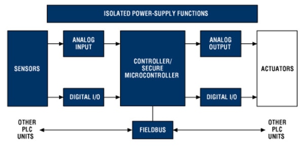
A typical industrial control system can be quite complex, comprising I/O modules for receiving information from sensors or sending out instructions to actuators, multichannel digital inputs, multichannel analog inputs and outputs, communications, and a PLC. Electrical power is supplied from the mains, stepped-down to the nominal system voltage and distributed via a backplane (Figure 1).

Figure 1: Schematic of industrial control system (Courtesy of Maxim Integrated).
Just to make things a little more difficult, designers of modern industrial control systems are under pressure to work within the confines of modular cabinets, tight budgets, and within tough thermal constraints. Modern silicon-based switching DC/DC voltage regulators meet many of these challenges. They are compact, efficient, and relatively inexpensive. They are increasingly popular as the basis of power supplies in consumer and automotive applications. However, such devices have been slow to catch on in industrial application because of one key drawback, an inability to handle high voltages.
Fortunately, improvements in design and manufacturing techniques have seen the maximum voltage capability creep up over the years, and modules rated for over 24 V operation are increasingly available. There are now even a few products that can directly handle input voltages up to the 48 V demanded of PoE.
Texas Instruments (TI) offers their TPS61170 in a tiny, 2 x 2 mm package. This step-up (“boost”), step-down (“buck”) regulator is based on a single-ended primary-inductor converter (SEPIC), can operate from a 3 to 18 V input, and can provide up to 38 V. It typically operates at 24 V output while supplying 150 mA at 93 percent efficiency from a 5 V supply.
For 48 V operation, Linear Technology offers their LT1074 100 kHz buck/boost regulator. The device can operate from an 8 to 64 V input and provide up to 50 V output at a maximum of 2 A.
Dealing with overvoltages
While it would seem perfectly reasonable to specify a regulator capable of handling up to 28 V for a 24 V system, or a 50 V power module for a 48 V control system, the nominal voltage is not the whole story. The designer also needs to take into account overvoltages that affect the mains supply (through events such as lighting strikes on the distribution network, or by rapid switching of heavy loads that share the same mains circuit as the industrial automation system) or within the power supply architecture itself (for example, from the power module that steps down the mains voltage, particularly if it is a switch-mode-type device).
These overvoltage occurrences are so common that organizations such as International Electrochemical Commission (IEC) advise engineers to design their systems to withstand them. IEC 60664, which deals with insulation coordination in “low-voltage” (1 kVAC and 1.5 kVDC) systems, notes that “Category-II” equipment (which includes the type of equipment used for industrial automation), powered from a mains-derived 24 VDC supply, should be designed to withstand overvoltages up to 60 V.
That presents a challenge because so-called high-voltage regulators are particularly sensitive to overvoltage. There is little margin between their operating and absolute maximum voltage ratings.
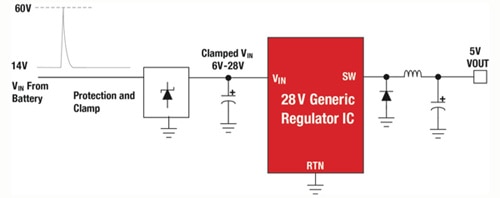
One solution is to protect the voltage regulator by using a protective clamp that limits the voltage spikes to a level below the component’s absolute maximum rated voltage (Figure 2). However, these clamps add cost, take up space, and extend the design schedule, negating many of the benefits for using a silicon-based voltage regulator in the first place.

Figure 2: A 28 V regulator protected from overvoltage by protective clamp (Courtesy of Texas Instruments).
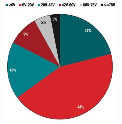
To overcome the need for protective clamps in industrial control circuits, semiconductor vendors have invested heavily in R&D, and now a few devices that can handle input voltages up to 60 or even 75 V are entering the market (Figure 3).

Figure 3: Voltage ratings of power controllers and regulators (Courtesy of Texas Instruments).
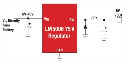
An example of these high-capability chips is the LM5006 from TI. This is a 3.1 x 3.1 mm, synchronous buck converter which can operate from a 6 to 75 V input while supplying up to 75 V at 600 mA at the output. Other features include thermal shutdown, maximum duty cycle limiter, programmable undervoltage detector with a status flag output, and a gate-driver output for a synchronous rectifier. The high input-voltage tolerance means the LM5006 can be used in applications where voltage spikes are expected without the need for protective clamping circuitry (Figure 4), saving cost, space, and design time.

Figure 4: The high input-voltage tolerance of TI’s LM5006 allows the designer to eliminate the protective clamping circuitry shown in Figure 2 (Courtesy of Texas Instruments).
It should be noted that although many high-voltage commercial voltage regulators can handle voltage spikes, this does not necessarily mean they will maintain perfect regulation during the transient event. The output may vary outside of normal operational limits but will not expose downstream circuitry to damaging overvoltages. The designer is advised to check the datasheet for a particular regulator’s performance under transient conditions.
Watch the current requirements
The use of high-voltage input regulators eases the development of an industrial control system because they eliminate the need for protective clamping circuits to shield the regulator from voltage spikes. However, that is not to say that the circuit design is simple.
A closer look at an industrial control system reveals greater complexity dictated by the varying voltage and current levels demanded by the various system elements. The 120/230 VAC mains supply is initially stepped down to the standard system backplane 24 or 48 VDC supply using an industrial power module. At the system level, this backplane voltage is then further stepped down to the lower voltage levels demanded by the individual components.

Figure 5: Industrial control systems require sophisticated power supplies to cope with the different voltage and current levels demanded by the various system elements (Courtesy of Maxim Integrated).
The PLC could comprise of a microprocessor, digital signal processor (DSP), and field programmable gate array (FPGA). These devices require voltages ranging from 5 down to 1 V, yet the PLC as a whole may require up to 3.5 A of current. Similarly, a multichannel analog I/O module requires both ±15 and 5 V supplies for its various amplifiers, analog-to-digital converters (ADCs), and multiplexers (MUXes) with current up to 500 mA.
Such a system will demand several regulators working in harmony operating from the supply bus and delivering the lower voltages at variable currents required by the silicon. Some manufacturers now offer families of voltage regulators designed to do just that.
Maxim offers their MAX1750x series, where the regulators in this family can all operate from 4.5 to 60 V inputs with outputs from 0.9 V. A key advantage of the range is that the designer can select a component with the current output required for a specific part of an industrial control system. At present the company offers devices with outputs of 300 and 500 mA, as well as 1 A, but says that it intends to extend the range to include devices with capabilities of “tens of milliamps to tens of amps.” The lower-current devices are useful for powering industrial automation system sensors on a 4 to 20 mA loop.
Users can choose devices with either pulse frequency modulation (PFM) or forced pulse width modulation (PWM) scheme. PFM devices skip pulses at light load for higher efficiency, while forced-PWM devices operate with fixed switching frequency at any load for noise-sensitive applications.
An example of one of these chips is the MAX17501. This chip is a synchronous type (integrating two MOSFETs and eliminating the external Schottky diode plus its associated external components). The MAX17501 comes in a 3 x 2 mm package and offers 85 percent efficiency (with an input of 24 V and at 450 mA output).
Not just for industrial control
High-voltage, high-output-current voltage regulators meet the industrial automation system designers’ demanding requirements for compact, efficient, and easy-to-design-in power modules. Due to their wide input-voltage tolerance, such devices are able to withstand the voltage spikes common to mains-powered industrial systems without the need for additional protective clamping circuitry.
The application of these devices is not limited to industrial control systems. They can also be useful when a designer wants an extra margin of safety and robustness. Even though a lower-voltage regulator might be a good choice in concept, a designer is wise to consider out-of-the-ordinary conditions that may happen only rarely in the lifetime of the product. Using a wide voltage-input regulator that is just as easy to use as its low-voltage counterpart provides peace of mind. The end product will feature a higher degree of reliability that may make the defining difference in the quality of otherwise comparable products.
Although the current selection of suitable components is limited, further products will be introduced in the near future to cover all of the DC/DC voltage-conversion requirements of a typical system across power outputs from a few tens of milliamps up to several Amps.
Further Reading:
- “Wide input voltage power management ICs simplify design, reduce BOM cost, and enhance reliability,” Vijay Choudhary, Texas Instruments white paper, 2013.
- “Introduction to Programmable Logic Controllers (PLCs) and the Operational Function of Main System Modules,” Hugh Wright, Maxim Integrated tutorial 4701, May, 2010
Disclaimer: The opinions, beliefs, and viewpoints expressed by the various authors and/or forum participants on this website do not necessarily reflect the opinions, beliefs, and viewpoints of DigiKey or official policies of DigiKey.


